Ubuntu ARM on ODROID-X2/X

We have made two major progresses of development on ARM Ubuntu for ODROID-X/X2.

1. Dual head display feature
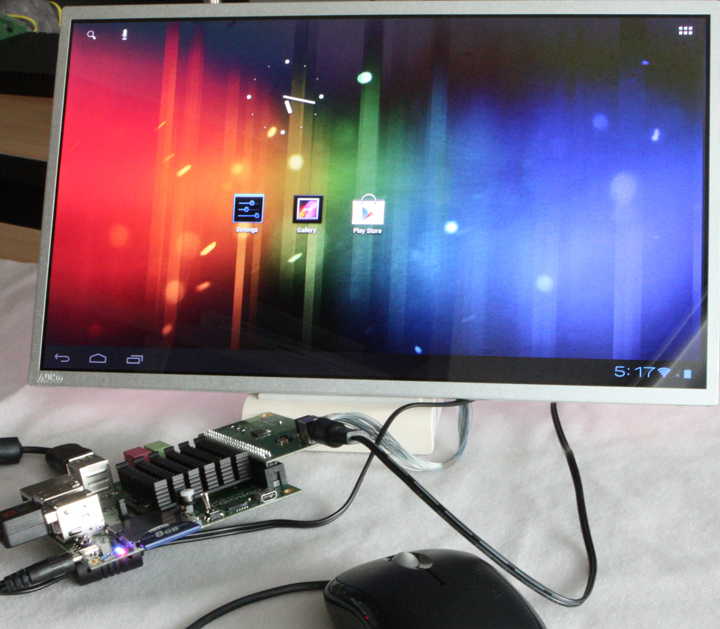
HDMI monitor of 1920×1080 resolution is working as a primary display.
LCD module of 1366×768 resolution is working as a secondary display. ( LCD Module kit information )
You can move the mouse cursor and window between the primary and secondary display.

2. eMMC device driver in Kernel 3.6.x
Now we can access the eMMC flash storage in Ubuntu/Linux.
mdrjr has committed his great port of eMMC driver into our github. Many thanks to him.
With this update, the OS booting time as well as overall performance is significantly improved.
We will release a brief guide for installation of Ubuntu on eMMC soon.

Enjoy this video and feel the boosted performance by eMMC and dual head display.

Here is our X11 configuration file for dual head display on ARM Ubuntu.
etc/X11/xorg.conf
Note that the framebuffer node name(fb0/fb6) may be different for each kernel configuration.

Section \"ServerFlags\"
        Option  \"Xinerama\"      \"true\"
        Option  \"DontZap\"
EndSection
Section \"Extensions\"
        #Option  \"Composite\"     \"Enable\"
        Option  \"Composite\"     \"Disable\"
        Option  \"RENDER\"        \"Enable\"
EndSection
Section \"Monitor\"
        Identifier      \"Monitor0\"
        VendorName      \"AOU\"
        ModelName       \"U133WA\"
        HorizSync       31.5 - 64.3
        VertRefresh     50 - 90
        Option          \"DPMS\"
EndSection
Section \"Monitor\"
        Identifier      \"Monitor1\"
        VendorName      \"LG\"
        ModelName       \"TV42\"
        HorizSync       21.5 - 63.4
        VertRefresh     50 - 90
        Option          \"DPMS\"
EndSection
Section \"Device\"
        identifier      \"LCD\"
        Driver          \"fbdev\"
        Option          \"fbdev\" \"/dev/fb0\"
EndSection
Section \"Device\"
        Identifier      \"HDMI\"
        Driver          \"fbdev\"
        Option          \"fbdev\" \"/dev/fb6\"
EndSection
Section \"Screen\"
        Identifier      \"Screen0\"
        Device          \"LCD\"
        Monitor         \"Monitor0\"
        DefaultDepth    16
        Subsection      \"Display\"
                Depth           16
                Modes           \"1360x768\"
                Virtual         2720 768
                ViewPort        0 0
        EndSubsection
EndSection
Section \"Screen\"
        Identifier      \"Screen1\"
        Device          \"HDMI\"
        Monitor         \"Monitor1\"
        DefaultDepth    16
EndSection
 
Section \"ServerLayout\"
        Identifier      \"Dual-Monitor\"
        Screen 0        \"Screen1\" 0 0
        Screen 1        \"Screen0\" RightOf \"Screen1\"
EndSection

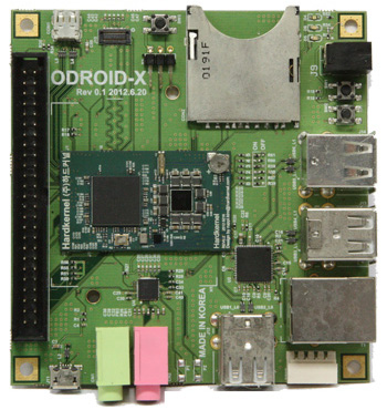
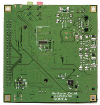
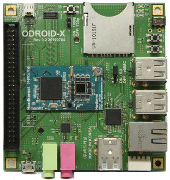
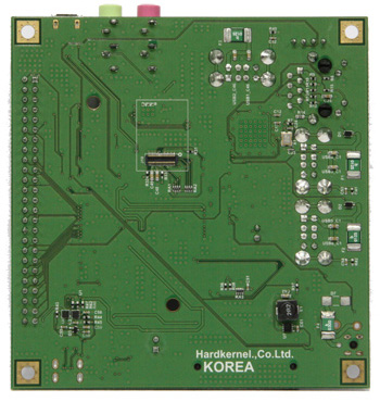
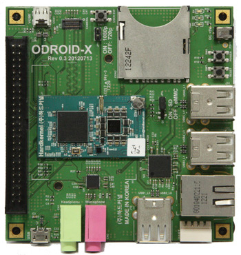
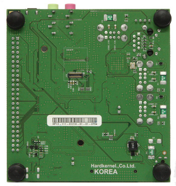
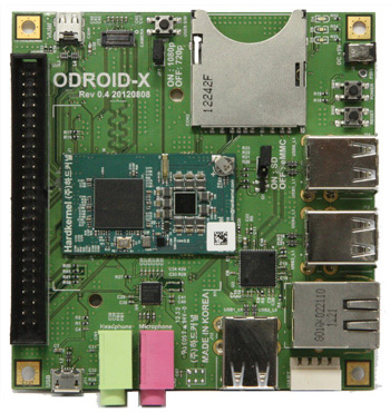
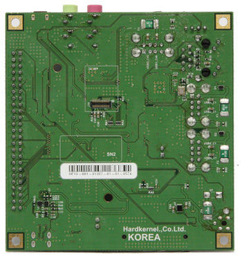
ODROID-X/X2 : History of PCB revision.

We have 4 revisions of ODROID-X/X2 base board up to now.

Rev 0.1  2012.6.20
First trial. Only for internal test purpose. We didn’t sell this revision.
We must cut some signal lines and added wires to make it work.
ODROID-X DC Jack wass identical to LCD board DC Jack.
But ODROID-X needs 5Volt and LCD board needs 9Volt.
So we killed many boards with wrong power supply due to confusion.

Rev 0.2  2012.7.04
Only for internal test purpose too. We didn’t sell this revision.
Changed DC Jack from 5.5mm to 2.1mm to prevent wrong plug/voltage.
Added more understanable texts on silk-screen printing.
Changed HDMI resolution setting jumper from 3pin to 2pin
Added SD/eMMC booting jumper instead resister soldering.

Rev 0.3  2012.7.13
This revision is used in the first mass production.
Slightly changed 5Volt input path.
Rubber foot added.
Heatsik added.
Shipped from end of July.

Rev 0.4  2012.8.08
3.3Volt Buck DCDC converter(U7) was changed from Ricoh RP505K331 to Torex XCL205B333.
This change was caused by market situation simply. There is no negative side effect.
We couldn’t purchase RP505K331 temporarily and we decided to replace it with XCL205B333 with minor modification of PCB.
Shipped from early September. Rev 0.3 and Rev 0.4 can be mixed for a while.

Download attached file which contains below schematics in PDF format.
– ODROID-X base board Rev 0.3
– ODROID-X base board Rev 0.4
– ODROID-X LCD board
– ODROID-X USB-UART board
– ODROID-X/Q eMMC board

Rev 0.5  2013.4.08
– Audio input circuit is modified for optimized mono-microphone input.
– Auto-power-on signal is hard-wired.
– HDMI reverse current blocking circuit is implemented.
– PCB silk change (ODROID-X to ODROID-X2+)
Shipped from early April 2013. Rev 0.5 and Rev 0.4 can be mixed for a while.

Rev 0.6 2014.4.18
http://dn.odroid.com/4412/Hardware/ODROID-X_BASE_Rev_06.pdf
– Added U1 AP2331 to completely block the HDMI leakage current.

Schematics of Exynos 4412 CPU Module will be available by email request to odroid@hardkernel.com with ODROID-X2 serial number which is printed on PCB. Please be noted that the serial number can be registered only once.

We do not have any plan to release schematics with other format at this moment.

Linux Kernel 3.6-rc1 runs Ubuntu 12.04 on ODROID-X

There are updates!
Read below article and jump to here to get the latest version.
http://odroid.foros-phpbb.com/t1171-linux-kernel-36-rc4-runs-ubuntu-1204-on-odroid-x

We’ve just made an initial port of Linux Kernel 3.6-rc1 which can run Ubuntu 12.04 with ODROID-X.
Note that Ubuntu root file system is came from Linaro 12.07 release. User ID and password are “linaro” and “linaro”.

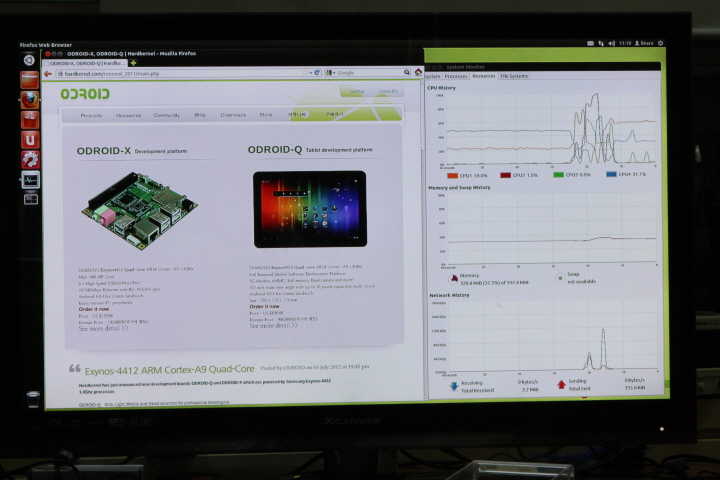
Here are some pictures show it runs Firefox and System-Monitor in Ubuntu.
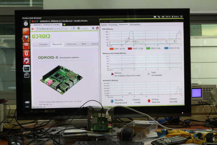
Ubuntu runs in 1080p mode
 

This is a full booting log with Ubuntu 12.04. We captured this log with USB-UART kit.

U-Boot 2010.12 (Aug 06 2012 - 11:50:16) for ODROID4412


CPU: S5PC220 [Samsung SOC on SMP Platform Base on ARM CortexA9]
APLL = 1000MHz, MPLL = 800MHz
DRAM:  1023 MiB

PMIC VERSION : 0x00, CHIP REV : 2

BL1 version: N/A (TrustZone Enabled BSP)


Checking Boot Mode ... SDMMC
REVISION: 1.1
MMC Device 0: 7695 MB
[ERROR] response timeout error : 00000104 cmd 1
FAIL: waiting for status update.
MMC Device 1: 0 MB
MMC Device 2 not found
ModeKey Check... run normal_boot
Net:   No ethernet found.
Hit any key to stop autoboot:  0
reading kernel..device 0 Start 1057, Count 16384
MMC read: dev # 0, block # 1057, count 16384 ... 16384 blocks read: OK
completed
Boot with zImage

Starting kernel ...

Uncompressing Linux... done, booting the kernel.
[    0.000000] Booting Linux on physical CPU 0
[    0.000000] Linux version 3.6.0-rc1 (ruppi@ruppi-Virtualbox) (gcc version 4.7.1 (Ubuntu/Linaro 4.7.1-5ubuntu1~ppa1) ) #5 SMP PREEMPT Tue Aug 7 13:39:13 KST 2012
[    0.000000] CPU: ARMv7 Processor [413fc090] revision 0 (ARMv7), cr=10c5387d
[    0.000000] CPU: PIPT / VIPT nonaliasing data cache, VIPT aliasing instruction cache
[    0.000000] Machine: ODROID-X
[    0.000000] cma: CMA: reserved 16 MiB at 6e800000
[    0.000000] Memory policy: ECC disabled, Data cache writealloc
[    0.000000] CPU EXYNOS4412 (id 0xe4412211)
[    0.000000] S3C24XX Clocks, Copyright 2004 Simtec Electronics
[    0.000000] s3c_register_clksrc: clock armclk has no registers set
[    0.000000] EXYNOS4: PLL settings, A=1000000000, M=800000000, E=96000000 V=108000000
[    0.000000] EXYNOS4: ARMCLK=1000000000, DMC=400000000, ACLK200=160000000
[    0.000000] ACLK100=100000000, ACLK160=160000000, ACLK133=133333333
[    0.000000] sclk_pwm: source is ext_xtal (0), rate is 24000000
[    0.000000] sclk_csis: source is xusbxti (1), rate is 1500000
[    0.000000] sclk_csis: source is xusbxti (1), rate is 1500000
[    0.000000] sclk_cam0: source is xusbxti (1), rate is 1500000
[    0.000000] sclk_cam1: source is xusbxti (1), rate is 1500000
[    0.000000] sclk_fimc: source is xusbxti (1), rate is 1500000
[    0.000000] sclk_fimc: source is xusbxti (1), rate is 1500000
[    0.000000] sclk_fimc: source is xusbxti (1), rate is 1500000
[    0.000000] sclk_fimc: source is xusbxti (1), rate is 1500000
[    0.000000] sclk_fimd: source is mout_mpll_user (6), rate is 50000000
[    0.000000] sclk_mfc: source is mout_mfc0 (0), rate is 50000000
[    0.000000] PERCPU: Embedded 7 pages/cpu @c0d65000 s7232 r8192 d13248 u32768
[    0.000000] Built 1 zonelists in Zone order, mobility grouping on.  Total pages: 255746
[    0.000000] Kernel command line: root=/dev/mmcblk0p3 rw rootfstype=ext4 init=/sbin/init console=ttySAC1,115200 console=tty1 rootdelay=2
[    0.000000] PID hash table entries: 4096 (order: 2, 16384 bytes)
[    0.000000] Dentry cache hash table entries: 131072 (order: 7, 524288 bytes)
[    0.000000] Inode-cache hash table entries: 65536 (order: 6, 262144 bytes)
[    0.000000] Memory: 48MB 216MB 743MB = 1007MB total
[    0.000000] Memory: 1000072k/1016456k available, 31096k reserved, 269312K highmem
[    0.000000] Virtual kernel memory layout:
[    0.000000]     vector  : 0xffff0000 - 0xffff1000   (   4 kB)
[    0.000000]     fixmap  : 0xfff00000 - 0xfffe0000   ( 896 kB)
[    0.000000]     vmalloc : 0xf0000000 - 0xff000000   ( 240 MB)
[    0.000000]     lowmem  : 0xc0000000 - 0xef800000   ( 760 MB)
[    0.000000]     pkmap   : 0xbfe00000 - 0xc0000000   (   2 MB)
[    0.000000]     modules : 0xbf000000 - 0xbfe00000   (  14 MB)
[    0.000000]       .text : 0xc0008000 - 0xc04a453c   (4722 kB)
[    0.000000]       .init : 0xc04a5000 - 0xc04ccc40   ( 160 kB)
[    0.000000]       .data : 0xc04ce000 - 0xc051e640   ( 322 kB)
[    0.000000]        .bss : 0xc051e664 - 0xc05577f0   ( 229 kB)
[    0.000000] SLUB: Genslabs=11, HWalign=64, Order=0-3, MinObjects=0, CPUs=4, Nodes=1
[    0.000000] Preemptible hierarchical RCU implementation.
[    0.000000] NR_IRQS:549
[    0.000000] sched_clock: 32 bits at 200 Hz, resolution 5000000ns, wraps every 4294967291ms
[    0.000000] Console: colour dummy device 80x30
[    0.000000] console [tty1] enabled
[    0.045000] Calibrating delay loop... 1992.29 BogoMIPS (lpj=4980736)
[    0.045000] pid_max: default: 32768 minimum: 301
[    0.045000] Mount-cache hash table entries: 512
[    0.045000] CPU: Testing write buffer coherency: ok
[    0.045000] CPU0: thread -1, cpu 0, socket 10, mpidr 80000a00
[    0.045000] hw perfevents: enabled with ARMv7 Cortex-A9 PMU driver, 7 counters available
[    0.045000] Setting up static identity map for 0x4036fdd8 - 0x4036fe30
[    0.045000] L310 cache controller enabled
[    0.045000] l2x0: 16 ways, CACHE_ID 0x4100c4c8, AUX_CTRL 0x7e470001, Cache size: 1048576 B
[    0.070000] CPU1: Booted secondary processor
[    0.090000] CPU1: thread -1, cpu 1, socket 10, mpidr 80000a01
[    0.090000] CPU1: Unknown IPI message 0x1
[    0.100000] CPU2: Booted secondary processor
[    0.120000] CPU2: thread -1, cpu 2, socket 10, mpidr 80000a02
[    0.120000] CPU2: Unknown IPI message 0x1
[    0.130000] CPU3: Booted secondary processor
[    0.150000] CPU3: thread -1, cpu 3, socket 10, mpidr 80000a03
[    0.150000] CPU3: Unknown IPI message 0x1
[    0.150000] Brought up 4 CPUs
[    0.150000] SMP: Total of 4 processors activated (7969.17 BogoMIPS).
[    0.155000] dummy:
[    0.155000] NET: Registered protocol family 16
[    0.160000] DMA: preallocated 256 KiB pool for atomic coherent allocations
[    0.165000] hw-breakpoint: found 5 (+1 reserved) breakpoint and 1 watchpoint registers.
[    0.165000] hw-breakpoint: maximum watchpoint size is 4 bytes.
[    0.165000] S3C Power Management, Copyright 2004 Simtec Electronics
[    0.165000] EXYNOS4x12 PMU Initialize
[    0.170000] EXYNOS: Initializing architecture
[    0.175000] bio: create slab at 0
[    0.180000] hdmi_5v: 5000 mV
[    0.180000] usbcore: registered new interface driver usbfs
[    0.180000] usbcore: registered new interface driver hub
[    0.180000] usbcore: registered new device driver usb
[    0.180000] s3c-i2c s3c2440-i2c.0: slave address 0x10
[    0.180000] s3c-i2c s3c2440-i2c.0: bus frequency set to 97 KHz
[    0.180000] max77686 0-0009: device found
[    0.180000] max77686 0-0009: irq is not specified
[    0.185000] LDO1 VDD_ALIVE: 1000 mV
[    0.185000] LDO2 VDDQ_M1_1V8: 1800 mV
[    0.190000] LDO3 VDDQ_AUD_1V8: 1800 mV
[    0.190000] LDO4 VDDQ_MMC2_2V8: 2800 mV
[    0.195000] LDO5 VDDQ_MMC1_1V8: 1800 mV
[    0.195000] LDO6 VDD10_MPLL_1V0: 1000 mV
[    0.200000] LDO7 VDD10_EPLL_1V0: 1000 mV
[    0.205000] LDO8 VDD10_MIPI_1V0: 1000 mV
[    0.205000] LDO9 VT_CORE_1V0: 1000 mV
[    0.210000] LDO10 VDD18_MIPI_1V8: 1800 mV
[    0.210000] vdd_ldo11 range: 1900 mV
[    0.215000] LDO12 VDD33_UOTG_3V3: 3300 mV
[    0.215000] LDO13 VDD18_MIPIHSI_1V8: 1800 mV
[    0.220000] vdd_ldo14 range: 1900 mV
[    0.225000] LDO15 VDD10_OTG: 1000 mV
[    0.225000] LDO16 VDD18_HSIC: 1800 mV
[    0.230000] LDO17 VDDQ_CAM_1V8: 1800 mV
[    0.230000] LDO18 VDDQ_ISP_1V8: 1800 mV
[    0.230000] LDO19 VT_CAM_1V8: 1800 mV
[    0.235000] LDO20 EMMC_IO_1V8: 1900 mV
[    0.235000] LDO21 TFLASH_2V8: 3300 mV
[    0.240000] LDO22: 3300 mV
[    0.240000] LDO23 VDD_TOUCH_2V8: 2800 mV
[    0.245000] LDO24 VDD_TOUCHLED_3V3: 3300 mV
[    0.245000] LDO25 VDDQ_LCD_1V8: 1800 mV
[    0.250000] LDO26 VDD_MOTOR_3V0: 3000 mV
[    0.250000] vdd_mif range: 800 <--> 1050 mV at 1000 mV
[    0.250000] vdd_arm range: 800 <--> 1350 mV at 1100 mV
[    0.255000] vdd_int range: 800 <--> 1150 mV at 1000 mV
[    0.255000] vdd_g3d range: 850 <--> 1200 mV at 1000 mV
[    0.255000] BUCK5 VDDQ_CKEM1_2: 1200 mV
[    0.260000] BUCK6 1V35: 1350 mV
[    0.265000] BUCK7 2V0: 2000 mV
[    0.265000] BUCK8 3V3: 3300 mV
[    0.270000] BUCK9 1V2: 1200 mV
[    0.270000] s3c-i2c s3c2440-i2c.0: i2c-0: S3C I2C adapter
[    0.270000] s3c-i2c s3c2440-i2c.1: slave address 0x10
[    0.270000] s3c-i2c s3c2440-i2c.1: bus frequency set to 97 KHz
[    0.270000] s3c-i2c s3c2440-i2c.1: i2c-1: S3C I2C adapter
[    0.270000] s3c-i2c s3c2440-i2c.3: slave address 0x10
[    0.270000] s3c-i2c s3c2440-i2c.3: bus frequency set to 97 KHz
[    0.270000] s3c-i2c s3c2440-i2c.3: i2c-3: S3C I2C adapter
[    0.270000] s3c-i2c s3c2440-i2c.7: slave address 0x10
[    0.270000] s3c-i2c s3c2440-i2c.7: bus frequency set to 97 KHz
[    0.270000] s3c-i2c s3c2440-i2c.7: i2c-7: S3C I2C adapter
[    0.270000] s3c-i2c s3c2440-hdmiphy-i2c: slave address 0x10
[    0.270000] s3c-i2c s3c2440-hdmiphy-i2c: bus frequency set to 97 KHz
[    0.270000] s3c-i2c s3c2440-hdmiphy-i2c: i2c-8: S3C I2C adapter
[    0.270000] Linux video capture interface: v2.00
[    0.270000] Advanced Linux Sound Architecture Driver Version 1.0.25.
[    0.270000] cfg80211: Calling CRDA to update world regulatory domain
[    0.270000] Switching to clocksource mct-frc
[    0.280000] NET: Registered protocol family 2
[    0.280000] TCP established hash table entries: 131072 (order: 8, 1048576 bytes)
[    0.280000] TCP bind hash table entries: 65536 (order: 8, 1572864 bytes)
[    0.280000] TCP: Hash tables configured (established 131072 bind 65536)
[    0.285000] TCP: reno registered
[    0.285000] UDP hash table entries: 512 (order: 3, 32768 bytes)
[    0.285000] UDP-Lite hash table entries: 512 (order: 3, 32768 bytes)
[    0.285000] NET: Registered protocol family 1
[    0.285000] bounce pool size: 64 pages
[    0.295000] msgmni has been set to 1459
[    0.295000] io scheduler noop registered
[    0.295000] io scheduler deadline registered
[    0.295000] io scheduler cfq registered (default)
[    0.295000] start plist test
[    0.300000] end plist test
[    0.300000] s3c-fb exynos4-fb.0: start latency exceeded, new value 750 ns
[    0.300000] s3c-fb exynos4-fb.0: state restore latency exceeded, new value 35500 ns
[    0.320000] Console: switching to colour frame buffer device 170x48
[    0.330000] s3c-fb exynos4-fb.0: window 0: fb
[    0.335000] dma-pl330 dma-pl330.0: Loaded driver for PL330 DMAC-267056
[    0.335000] dma-pl330 dma-pl330.0:     DBUFF-32x4bytes Num_Chans-8 Num_Peri-32 Num_Events-32
[    0.340000] dma-pl330 dma-pl330.1: Loaded driver for PL330 DMAC-267056
[    0.340000] dma-pl330 dma-pl330.1:     DBUFF-32x4bytes Num_Chans-8 Num_Peri-32 Num_Events-32
[    0.345000] dma-pl330 dma-pl330.2: Loaded driver for PL330 DMAC-267056
[    0.345000] dma-pl330 dma-pl330.2:     DBUFF-64x8bytes Num_Chans-8 Num_Peri-1 Num_Events-32
[    0.405000] Serial: 8250/16550 driver, 4 ports, IRQ sharing disabled
[    0.410000] exynos4210-uart.0: ttySAC0 at MMIO 0x13800000 (irq = 84) is a S3C6400/10
[    0.410000] exynos4210-uart.1: ttySAC1 at MMIO 0x13810000 (irq = 85) is a S3C6400/10
[    1.280000] console [ttySAC1] enabled
[    1.285000] exynos4210-uart.2: ttySAC2 at MMIO 0x13820000 (irq = 86) is a S3C6400/10
[    1.295000] exynos4210-uart.3: ttySAC3 at MMIO 0x13830000 (irq = 87) is a S3C6400/10
[    1.310000] brd: module loaded
[    1.315000] loop: module loaded
[    1.320000] ehci_hcd: USB 2.0 'Enhanced' Host Controller (EHCI) Driver
[    1.320000] s5p-ehci s5p-ehci: S5P EHCI Host Controller
[    1.325000] s5p-ehci s5p-ehci: new USB bus registered, assigned bus number 1
[    1.335000] s5p-ehci s5p-ehci: irq 102, io mem 0x12580000
[    1.350000] s5p-ehci s5p-ehci: USB 2.0 started, EHCI 1.00
[    1.350000] usb usb1: New USB device found, idVendor=1d6b, idProduct=0002
[    1.355000] usb usb1: New USB device strings: Mfr=3, Product=2, SerialNumber=1
[    1.365000] usb usb1: Product: S5P EHCI Host Controller
[    1.370000] usb usb1: Manufacturer: Linux 3.6.0-rc1 ehci_hcd
[    1.375000] usb usb1: SerialNumber: s5p-ehci
[    1.380000] hub 1-0:1.0: USB hub found
[    1.385000] hub 1-0:1.0: 3 ports detected
[    1.385000] ohci_hcd: USB 1.1 'Open' Host Controller (OHCI) Driver
[    1.395000] exynos-ohci exynos-ohci: Already power on PHY
[    1.400000] exynos-ohci exynos-ohci: EXYNOS OHCI Host Controller
[    1.405000] exynos-ohci exynos-ohci: new USB bus registered, assigned bus number 2
[    1.410000] exynos-ohci exynos-ohci: irq 102, io mem 0x12590000
[    1.475000] usb usb2: New USB device found, idVendor=1d6b, idProduct=0001
[    1.480000] usb usb2: New USB device strings: Mfr=3, Product=2, SerialNumber=1
[    1.490000] usb usb2: Product: EXYNOS OHCI Host Controller
[    1.495000] usb usb2: Manufacturer: Linux 3.6.0-rc1 ohci_hcd
[    1.500000] usb usb2: SerialNumber: exynos-ohci
[    1.505000] hub 2-0:1.0: USB hub found
[    1.505000] hub 2-0:1.0: 3 ports detected
[    1.510000] usb3503: USB HUB driver init
[    1.515000] usb3503: usb3503_probe:375
[    1.520000] usb3503: usb3503_set_mode: mode = 1
[    1.630000] usb3503: usb3503_register_write: reg: e7 data: 3 write failed
[    1.630000] usb3503: reg_write: write E7, req:03, val:00
[    1.635000] usb3503: SP_ILOCK write fail err = -111
[    1.640000] usb3503: usb3503_probe: probed on  hub mode
[    1.645000] i2c-core: driver [usb3503] using legacy suspend method
[    1.655000] i2c-core: driver [usb3503] using legacy resume method
[    1.660000] s3c-rtc s3c64xx-rtc: rtc disabled, re-enabling
[    1.665000] s3c-rtc s3c64xx-rtc: rtc core: registered s3c as rtc0
[    1.670000] s5p-hdmiphy 8-0038: probe successful
[    1.685000] s5p-hdmi exynos4-hdmi: probe successful
[    1.690000] Samsung TV Mixer driver, (c) 2010-2011 Samsung Electronics Co., Ltd.
[    1.695000] s5p-mixer s5p-mixer: probe start
[    1.700000] s5p-mixer s5p-mixer: resources acquired
[    1.705000] s5p-mixer s5p-mixer: added output 'S5P HDMI connector' from module 's5p-hdmi'
[    1.710000] s5p-mixer s5p-mixer: module s5p-sdo is missing
[    1.715000] s5p-mixer s5p-mixer: registered layer graph0 as /dev/video0
[    1.725000] fb1: registered frame buffer emulation for /dev/video0
[    1.730000] s5p-mixer s5p-mixer: registered layer graph1 as /dev/video1
[    1.735000] fb2: registered frame buffer emulation for /dev/video1
[    1.745000] s5p-mixer s5p-mixer: registered layer video0 as /dev/video2
[    1.750000] fb3: registered frame buffer emulation for /dev/video2
[    1.755000] s5p-mixer s5p-mixer: probe successful
[    1.760000] sdhci: Secure Digital Host Controller Interface driver
[    1.765000] sdhci: Copyright(c) Pierre Ossman
[    1.770000] s3c-sdhci exynos4-sdhci.2: clock source 2: mmc_busclk.2 (88888888 Hz)
[    1.780000] mmc0: no vmmc regulator found
[    1.810000] mmc0: SDHCI controller on samsung-hsmmc [exynos4-sdhci.2] using ADMA
[    1.810000] s3c-sdhci exynos4-sdhci.3: clock source 2: mmc_busclk.2 (88888888 Hz)
[    1.820000] mmc1: no vmmc regulator found
[    1.850000] mmc0: new high speed SDHC card at address b368
[    1.855000] usb 1-2: new high-speed USB device number 2 using s5p-ehci
[    1.860000] mmc1: SDHCI controller on samsung-hsmmc [exynos4-sdhci.3] using ADMA
[    1.870000] mmcblk0: mmc0:b368 00000 7.51 GiB
[    1.870000] usbcore: registered new interface driver usbhid
[    1.870000] usbhid: USB HID core driver
[    1.870000] TCP: cubic registered
[    1.870000] NET: Registered protocol family 17
[    1.870000] NET: Registered protocol family 15
[    1.870000] NET: Registered protocol family 35
[    1.900000] VFP support v0.3: implementor 41 architecture 3 part 30 variant 9 rev 4
[    1.900000]  mmcblk0: p1 p2 p3
[    1.910000] Registering SWP/SWPB emulation handler
[    1.915000] vdd_g3d range: incomplete constraints, leaving on
[    1.920000] LDO25 VDDQ_LCD_1V8: incomplete constraints, leaving on
[    1.925000] s3c-rtc s3c64xx-rtc: setting system clock to 2012-08-07 08:30:44 UTC (1344328244)
[    1.935000] ALSA device list:
[    1.935000]   No soundcards found.
[    1.940000] Waiting 2sec before mounting root device...
[    1.990000] usb 1-2: New USB device found, idVendor=0424, idProduct=3503
[    1.990000] usb 1-2: New USB device strings: Mfr=0, Product=0, SerialNumber=0
[    2.000000] hub 1-2:1.0: USB hub found
[    2.005000] hub 1-2:1.0: 3 ports detected
[    2.295000] usb 1-2.1: new high-speed USB device number 3 using s5p-ehci
[    2.400000] usb 1-2.1: New USB device found, idVendor=0424, idProduct=9514
[    2.400000] usb 1-2.1: New USB device strings: Mfr=0, Product=0, SerialNumber=0
[    2.410000] hub 1-2.1:1.0: USB hub found
[    2.415000] hub 1-2.1:1.0: 5 ports detected
[    2.705000] usb 1-2.1.1: new high-speed USB device number 4 using s5p-ehci
[    2.810000] usb 1-2.1.1: New USB device found, idVendor=0424, idProduct=ec00
[    2.810000] usb 1-2.1.1: New USB device strings: Mfr=0, Product=0, SerialNumber=0
[    2.910000] usb 1-2.1.3: new low-speed USB device number 5 using s5p-ehci
[    3.005000] usb 1-2.1.3: New USB device found, idVendor=15d9, idProduct=0a4c
[    3.010000] usb 1-2.1.3: New USB device strings: Mfr=0, Product=1, SerialNumber=0
[    3.020000] usb 1-2.1.3: Product:  USB OPTICAL MOUSE
[    3.025000] input:  USB OPTICAL MOUSE as /devices/platform/s5p-ehci/usb1/1-2/1-2.1/1-2.1.3/1-2.1.3:1.0/input/input0
[    3.035000] hid-generic 0003:15D9:0A4C.0001: input,hidraw0: USB HID v1.11 Mouse [ USB OPTICAL MOUSE] on usb-s5p-ehci-2.1.3/input0
[    3.130000] usb 1-2.1.5: new low-speed USB device number 6 using s5p-ehci
[    3.250000] usb 1-2.1.5: New USB device found, idVendor=04d9, idProduct=1203
[    3.255000] usb 1-2.1.5: New USB device strings: Mfr=0, Product=0, SerialNumber=0
[    3.275000] input: HID 04d9:1203 as /devices/platform/s5p-ehci/usb1/1-2/1-2.1/1-2.1.5/1-2.1.5:1.0/input/input1
[    3.280000] hid-generic 0003:04D9:1203.0002: input,hidraw1: USB HID v1.11 Keyboard [HID 04d9:1203] on usb-s5p-ehci-2.1.5/input0
[    3.310000] input: HID 04d9:1203 as /devices/platform/s5p-ehci/usb1/1-2/1-2.1/1-2.1.5/1-2.1.5:1.1/input/input2
[    3.315000] hid-generic 0003:04D9:1203.0003: input,hidraw2: USB HID v1.11 Device [HID 04d9:1203] on usb-s5p-ehci-2.1.5/input1
[   12.310000] EXT4-fs (mmcblk0p3): 4 orphan inodes deleted
[   12.310000] EXT4-fs (mmcblk0p3): recovery complete
[   13.685000] EXT4-fs (mmcblk0p3): mounted filesystem with ordered data mode. Opts: (null)
[   13.690000] VFS: Mounted root (ext4 filesystem) on device 179:3.
[   13.695000] Freeing init memory: 156K
[   21.075000] s3c-hsotg s3c-hsotg: Failed to get supply 'vusb_d': -517
[   21.080000] s3c-hsotg s3c-hsotg: failed to request supplies: -517
[   21.585000] init: Failed to create pty - disabling logging for job
[   21.605000] init: Failed to create pty - disabling logging for job
[   21.695000] init: Failed to create pty - disabling logging for job
[   21.710000] init: Failed to create pty - disabling logging for job
[   21.895000] s3c-hsotg s3c-hsotg: Failed to get supply 'vusb_d': -517
[   21.900000] s3c-hsotg s3c-hsotg: failed to request supplies: -517
[   22.505000] init: Failed to create pty - disabling logging for job
[   22.795000] init: Failed to create pty - disabling logging for job
[   22.815000] init: Failed to create pty - disabling logging for job
[   22.820000] init: Failed to create pty - disabling logging for job
[   23.275000] init: Failed to create pty - disabling logging for job
[   23.295000] init: Failed to create pty - disabling logging for job
[   23.305000] init: Failed to create pty - disabling logging for job
[   23.310000] init: Failed to create pty - disabling logging for job
[   23.320000] init: Failed to create pty - disabling logging for job
[   23.325000] init: Failed to create pty - disabling logging for job

[   23.345000] init: Failed to create pty - disabling logging for job
[   23.405000] init: Failed to create pty - disabling logging for job
[   23.410000] init: Failed to create pty - disabling logging for job
[   23.425000] init: Failed to create pty - disabling logging for job
[   23.430000] init: Failed to create pty - disabling logging for job
[   23.435000] init: Failed to create pty - disabling logging for job
[   23.445000] init: Failed to create pty - disabling logging for job
[   23.450000] init: Failed to create pty - disabling logging for job
[   23.455000] init: Failed to create pty - disabling logging for job
[   23.460000] init: Failed to create pty - disabling logging for job
[   23.475000] init: Failed to create pty - disabling logging for job
[   23.495000] init: Failed to create pty - disabling logging for job
[   23.820000] init: Failed to create pty - disabling logging for job
[   23.840000] init: Failed to create pty - disabling logging for job
Last login: Tue Aug  7 07:54:18 UTC 2012 on tty1
Welcome to Linaro 12.07 (GNU/Linux 3.6.0-rc1 armv7l)

* Documentation:  https://wiki.linaro.org/

106 packages can be updated.
20 updates are security updates.

root@linaro-ubuntu-desktop:~#


Yes!
There are many points to reduce the booting time.
Let’s find how to improve it!

We’ve implemented and tested below features.
– Linux Kernel 3.6-rc1 with gcc 4.7.1 Linaro toolchain
– SMP driven Quad-Core processing
– PMIC device driver
– USB 2.0 High-speed Host driver for Exynos-4412 HSIC interface
– Ethernet + USB Hub device driver
– LCD display driver
– HDMI display driver (Very early version and it may have HDMI 1.4a compatibility issues with some monitors)

Known issues.
– Audio codec driver is not ported (We will implement this within couple of weeks)
– eMMC device driver is not ported (We will implement this within couple of weeks)
– Clock control driver is not ported (We will change the default clock from 1Ghz to 1.5Ghz soon)
– 3D HW-GPU X11 driver is not ready (This may need couple of months)
– Power-off  (Power off function of Ubuntu GUI is not working. There is no way to power off except for unplugging DC plug. OTL)
– WiFi module is not working with Ubuntu GUI. (Command line of Wireless-tools may work)
– Many other issues

This WiKi describes how to build it and how to use pre-built image for SD-card.
http://dev.odroid.com/projects/odroid-xq/#s-3.2

You can download the pre-built images from this bit-torrent.
bit-torrent Ubuntu-ODROIDX
There are two different pre-built images.
#1. Image file for LCD display
#2. Image file for HDMI display

Please note this version doesn’t support eMMC. So you must plug JP2-jumper.
If your HDMI monitor supports only 720p, you must unplug JP1-jumper. If your monitor supports 1080p, plug JP1-jumper.
We need to implement automatic detection function in future.

Refer below picture to know where is JP1 & JP2.
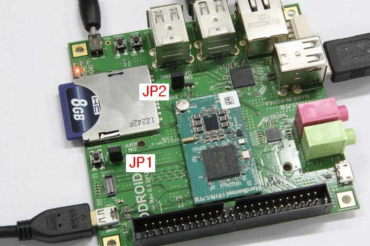
SD Card setup for ODROID-X

To boot the ODROID-X/X2/U/U2, you need an SD card or eMMC module installed with a bootloader and a suitable Operating System.

Some ODROID kits will come with a ready-to-go card, but if you didn’t purchase one you will need to prepare your own:

Official images are available in this link.

Warning! When you write the ODROID image to your SD card you will lose all data that was on the card.


Copying the image to an SD Card on Windows

  1. Download a zipped image from this link or other mirrors
  2. Extract the image file .img or .odt from the zip file.
  3. Insert the SD card into your SD card reader and check what drive letter it was assigned. You can easily see the drive letter (for example G:) by looking in the left column of Windows Explorer. If the card is not new, you should format it; otherwise Win32DiskImager may hang.
  4. Download the Win32DiskImager utility. The download links are on the right hand side of the page, you want the binary zip.
  5. Extract the zip file and run the Win32DiskImager utility. You may need to run the utility as Administrator.
  6. Select the *.img image file you extracted earlier
  7. Select the drive letter of the SD card in the device box. Be careful to select the correct drive; if you get the wrong one you can destroy your computer’s hard disk!
  8. Click Write and wait for the write to complete.
  9. Exit the imager and eject the SD card.
  10. Insert the card in the ODROID, power it on, and it should boot up. Have fun!


Copying an image to the SD Card in Linux (command line)

Please note that the use of the “dd” tool can overwrite any partition of your machine. If you specify the wrong device in the instructions below you could delete your primary Linux partition. Please be careful.

  1. Download a zipped image from this link or other mirrors
  2. Extract the image, with (just an example)
    • unzip ~/OdroidX_image_31-Jul-2012.zip
  3. Run df -h to see what devices are currently mounted
  4. If your computer has a slot for SD cards, insert the card. If not, insert the card into an SD card reader, then connect the reader to your computer.
  5. Run df -h again. The device that wasn’t there last time is your SD card. The left column gives the device name of your SD card. It will be listed as something like “/dev/mmcblk0p1” or “/dev/sdd1”. The last part (“p1” or “1” respectively) is the partition number, but you want to write to the whole SD card, not just one partition, so you need to remove that part from the name (getting for example “/dev/mmcblk0” or “/dev/sdd”) as the device for the whole SD card. Note that the SD card can show up more than once in the output of df: in fact it will if you have previously written a ODROID image to this SD card, because the ODROID SD images have more than one partition.
  6. Now that you’ve noted what the device name is, you need to unmount it so that files can’t be read or written to the SD card while you are copying over the SD image. So run the command below, replacing “/dev/sdd1” with whatever your SD card’s device name is (including the partition number)
    • umount /dev/sdd1
    • Note that if you are not logged in as root you will need to prefix this with sudo
    • If your SD card shows up more than once in the output of df due to having multiple partitions on the SD card, you should unmount all of these partitions.
  7. In the terminal write the image to the card with this command, making sure you replace the input file if= argument with the path to your .img file, and the “/dev/sdd” in the output file of= argument with the right device name (this is very important: you will lose all data on the hard drive on your computer if you get the wrong device name). Make sure the device name is the name of the whole SD card as described above, not just a partition of it (for example, sdd, not sdds1 or sddp1, or mmcblk0 not mmcblk0p1)
    • dd bs=1M if=ODROID-X_31_07_2012.img of=/dev/sdd
    • Note that if you are not logged in as root you will need to prefix this with sudo
    • The dd command does not give any information of its progress and so may appear to have frozen. It could take more than five minutes to finish writing to the card. If your card reader has an LED it may blink during the write process, or you can run pkill -USR1 -n -x dd in another terminal (prefixed with sudo if you are not logged in as root).
  8. As root run the command sync or if a normal user run sudo sync (this will ensure the write cache is flushed and that it is safe to unmount your SD card)
  9. Remove SD card from card reader, insert it in the ODROID, and have fun

Copying an image to the SD Card in Linux (graphical interface)

If you are using Ubuntu and hesitate to use the terminal, you can use the ImageWriter tool (nice graphical user interface) to write the .img file to the SD card.

  1. Download a zipped image from this link or other mirrors
  2. Right click the zip file and select “Extract here”
    • ATTENTION: As of this writing (15 June 2012), there is a bug in the ImageWriter program that causes it to fail if the filename of the image file or its path (i.e. all the names of any parent folders that you extract the image file into) contain any space characters. Before going any further, ensure that neither the file name of the image you’re using or the path contain any spaces (or other odd characters, for that matter). A bug has been opened for this issue: https://bugs.launchpad.net/usb-imagewriter/+bug/1013834 Once the issue is fixed, edit this page to advise people to use an updated/patched version of ImageWriter.
  3. Insert the SD card into your computer or connect the SD card reader with the SD card inside
  4. Install the ImageWriter tool from the Ubuntu Software Center
  5. Launch the ImageWriter tool (it needs your administrative password)
  6. Select the image file (example ODROID-X_31_07_2012.img) to be written to the SD card (note: because you started ImageWriter as administrator the starting point when selecting the image file is the administrator’s home folder so you need to change to your own home folder to select the image file)
  7. Select the target device to write the image to (your device will be something like “/dev/mmcblk0” or “/dev/sdc”)
  8. Click the “Write to device” button
  9. Wait for the process to finish and then insert the SD card in the ODROID

Manually resizing the SD card partitions (Optional)

The SD card image is sized for a 8GB card. The Fedora Remix will automatically resize the partitions on the card during the first boot. The Debian version won’t, so you’ll have to do it manually. It’s much easier if you do this on another machine, as the SD card can’t be mounted when you do this.

Look here for instructions.

Please note most of those instructions came from famouse RPi WiKi.

ODROID-X & X2 Schematics

Download ODROID-X_BASE_REV0.5.pdf

Download ODROID-X_schematics.zip

ODROID-X schematics has beed released now.
List of schematics above link is as below. The format of schematics is PDF.

– ODROID-X Baseboard
– USB-UART Board 
– LCD Module Board
– eMMC Module Board


Schematics of Exynos 4412 CPU Module will be available by email request to odroid@hardkernel.com with ODROID-X/X2 serial number which is printed on PCB. Please be noted that the serial number can be registered only once. 

We do not have any plan to open schematics with other format at this moment.

USB-UART Module Kit

There is a system console port in all of ODROID series to monitor the low-level information of target system.
This is very useful and important tool for platform software development.

The system console port uses UART(Universal asynchronous receiver/transmitter) of CPU for communication between your host PC and target board.
Protocol is 115200bps / no-parity / 8bit / 1-stop-bit / No-flowcontrol as usual.
You can use any tty terminal software such puTTY, minicom or hyperTerminal in your host PC.

The UART of CPU has simple 2 signals Tx and Rx with a ground level for communication.
Please note most of new comming mobile processors have 1.8V of IO voltage to minimize power consumption.

In traditional design, there should be a RS-232C level converter MAX232 or MAX3232 or MAX3218 on board.
Addtionally your Host PC must have a RS-232C port.
Note that all of modern PC / Laptop have no built-in RS-232C port you have to buy a USB-RS232 converter.
So this solution is expensive, uncomfortable and bigger footprint.

Fortunately, there are many IC makers have introduced USB-UART bridge ICs.

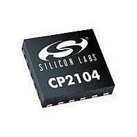
To meet the low voltage interface specification. we chose the CP2104 USB-UART bridge IC from the Silicon Labs.
You can find the datasheet of CP2104 and its drivers from this link.
http://www.silabs.com/products/interface/usbtouart/Pages/usb-to-uart-bridge.aspx

CP2104 has internal oscillator, LDO, Tx/Rx indicating LED drivers and 1.8Volt IO with reasonable price in 4mmx4mm package.


USB-UART Module kit contains below 3 items.- Micro-USB cable
– USB-UART board with CP2104
– 4pin wire harness to connect to ODROID-X


Let’s look into USB-UART board.
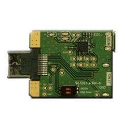
You can find Micro-USB connector, 4-pin Wire-connector, USB-UART bridge IC CP2104 and 3 LED inticator on top side.
D1 is Tx LED, D2 is Rx LED and D3 is power indicator. Note this board is powered by USB of host PC.
On bottom side, there are some passive devices and USB signal conditioner of L1.

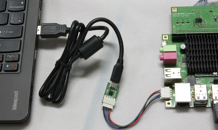
Place the 4pin wire harness between USB-UART board and your ODROID-X/X2/U2/U3/C1/XU3/XU as below picture.
And place the Micro-USB cable between your host PC and USB-UART board.

You can download proper device drivers for your host PC.
Click “Tools” tab to get drivers for Windows, Mac and Linux in this link.
http://www.silabs.com/products/interface/usbtouart/Pages/usb-to-uart-bridge.aspx

I want to let you know some information of CP2104 device driver for your host Linux PC.
If your host Linux PC runs Kernel 3.2 or higher, the CP2104 works without any addtional installation/compilation.
Note Ubuntu 12.04 is based on Kernel 3.2.

This is a USB-UART board for ODROID-Q model which also has CP2104.
We call it “Debug board” from time to time.

LCD Module Kits for ODROID-X

There are two different LCD module kits for ODROID-X.
One is 10.1inch and the other is 13.3inch.
Resolution and other characteristics are almost identical. Yes. The only difference is the dimension.

Please note the 10.1inch model was all sold out.

BTW, we have one news to whom have purchased 13.3 inch LCD Kit.
We have tested 13.3 inch and 14 inch LCD modules together. 13.3 inch LCD price is lower but it’s weak since the PCB is outside of LCD frame. 14 inch LCD price is higher but PCB is well located on the back side of LCD. So, we have decided to provide 14 inch upgrade version without any cost to whom purchase 13.3 inch LCD Kit.

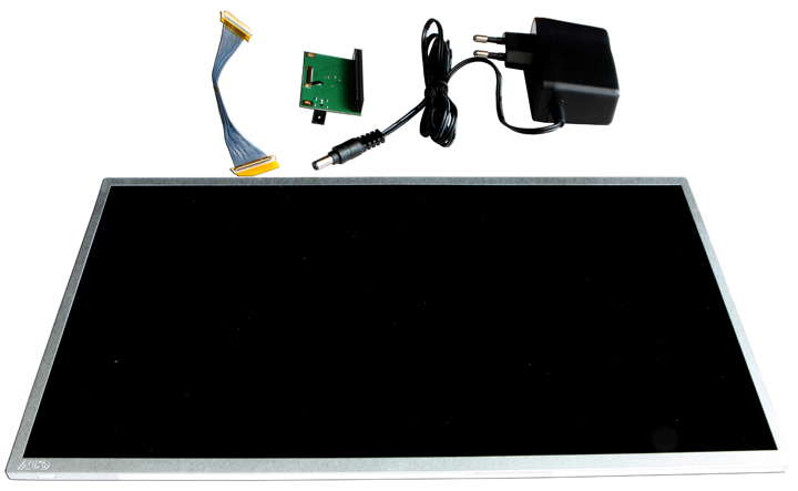
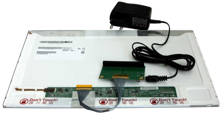
LCD Module kit contains below items.

– LCD module
– LCD interface board
– LVDS cable
– DC Adaptor ( 9Volt / 1.5Amp )

If we assemble this kit….

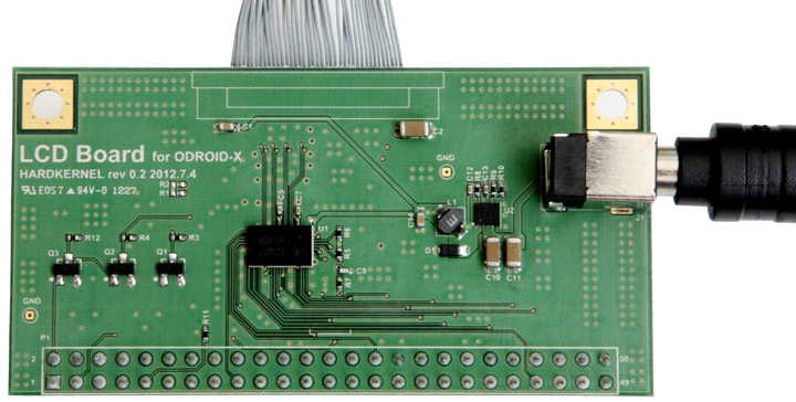
You might want to look into the interface board more closely.

It has a RGB-LVDS converter IC and 3.3Volt step-down DCDC converter.
We used TI’s SN75LVDS83BZ and Ricoh’s R1240K003B respectively.
Here is a picture of top-side.


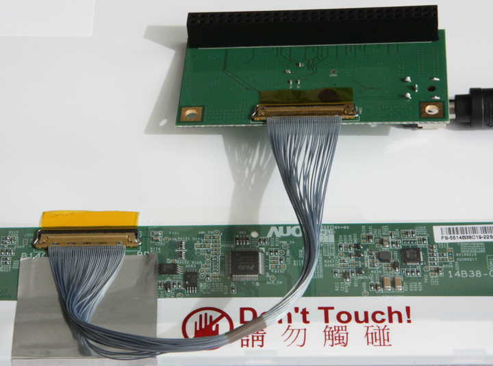
This picture shows bottom-side and LCD connection.


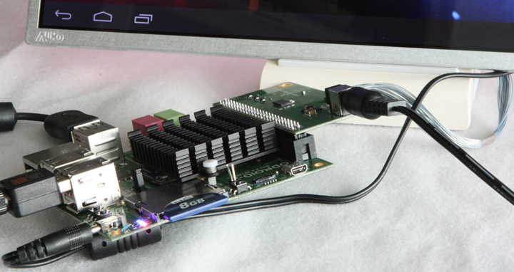
It’s time to plug the LCD interface board into ODROID-X 50-pin connector.


Another shot !


You can find the datasheed of LCD in this link.
10.1 inch LCD <== Click this.

Note: The LCD module may be a compatible product due to market condition.

ODROID-X & ODROID-Q Shipment Ready

ODROID-X and ODROID-Q production has started this week. We will start the shipment from next week. Please refer to the below for the shipment schedule.

– 1st batch from 30th of July : your order between 1st of July and 11th of July : Shipped out 
– 2nd batch from 6th of August : your order between 12th of July and 15th of July : Shipped out 
– 3rd batch from 13th of August : your order between 16th of July and 31st of July :  Shipped out 
– 4th batch from 27th of August : your order between 1st of August and 6th of August : Shipped out
– 5th batch from 3rd of September : your order between 7th of August and 17th of August : Shipped out
– 6th batch from 10th of September : your order between 18th of August and 31th of August : Shipped out

– After all :  in two weeks after your purchasing!
 
The delivery takes around 3-5 days after you receive the tracking number. But, it depends on your country’s customs process. The tracking number will be sent via paypal linked email or Fedex system. Please check your order’s delivery status after you get the tracking number here. 
Fedex : http://www.fedex.com/
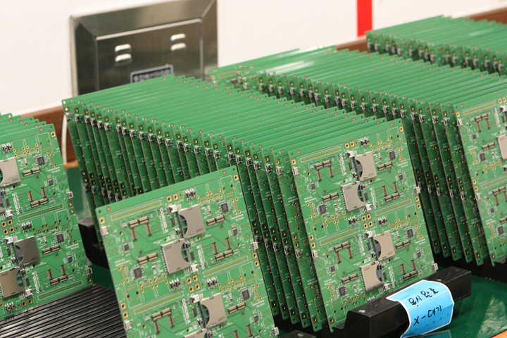
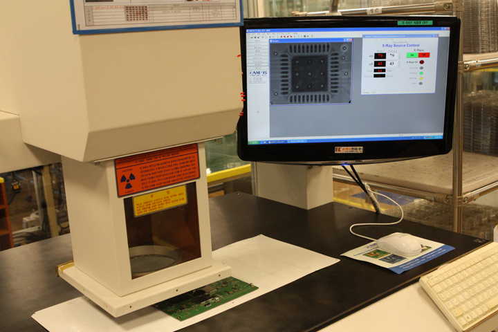
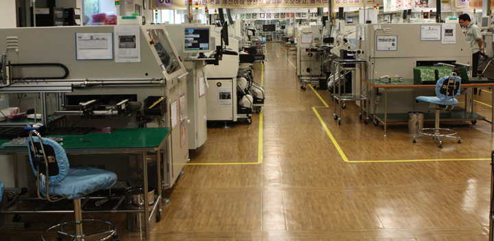
The pictures of production line are below. 
 
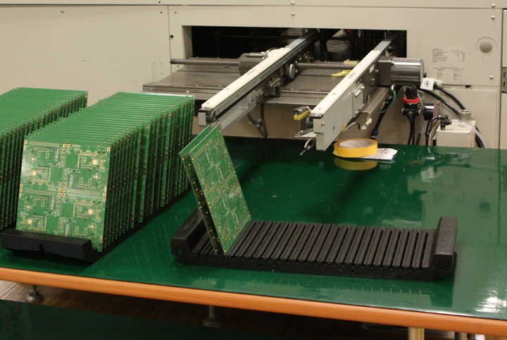
1. First stage of  process. The machine is “Solder cream printer”.


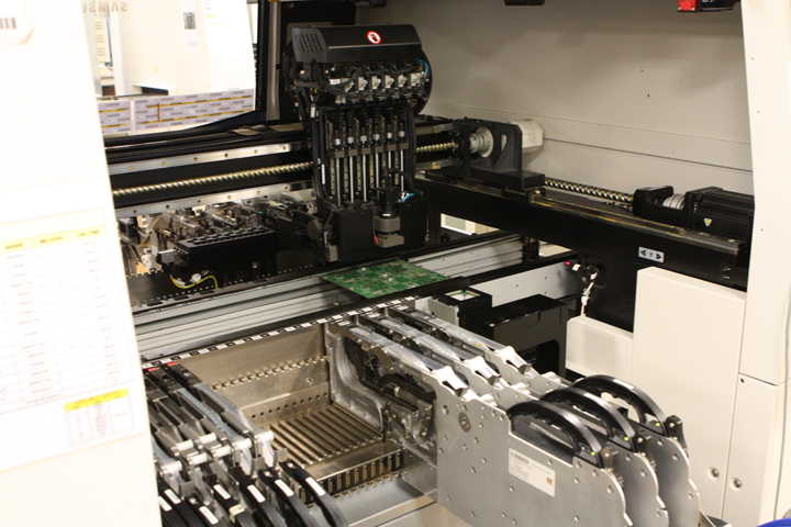
2. SMT machine: Mouting devices on the PCB.


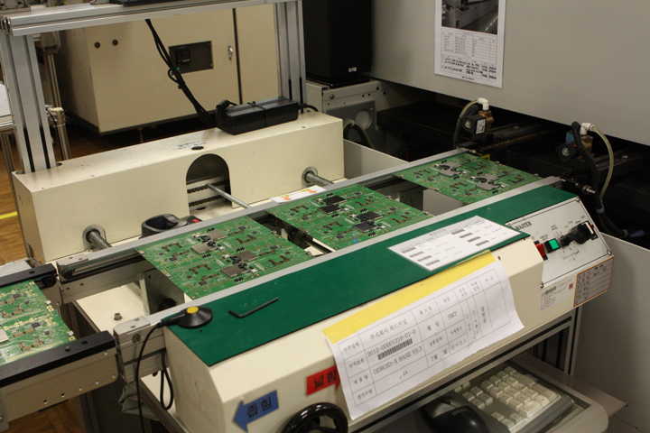
3. Entering into reflow soldering machine.


4. SMT soldering is done. Ready to inpection process.

* Note: Each board has 2×2 array of actual PCB to increase the production efficiency.

5. X-ray inspection to check soldering quality.


6. Factory Lines

The PCBs will move to another soldering machine for various connectors after inspection process.
And then we will perform all the functionality tests.

High-Definition Games on ODROID-X

Many users requested us to make a video of game play.
Please remember the ODROID-X was designed for developers.
But we also really want to enjoy exciting games too. 🙂

I heard some games support USB joystick input-event handler in Android platform.
So I got a Xbox 360 Wired Controller from my house. My kids may be crying now. 🙂

Anyway, we must configure Kernel options to activate the Xbox contoller for Android USB interface.
Search with ‘xpad’ in Kerenl menuconfig screen and enable all the related items. Recompile the Kernel and just transfer the zImage into ODROID-X.
We will set this configuration as a default when we ship the ODROID-X.

The first game we tried is “SHADOW GUN”. It is one of the best shooting game for Android.
It ain’t just pretty—it’s gorgeous! Advanced lighting effects, beautifully rendered environments, and pro voices make
this one of the most advanced games for your Android device!


The second game is “DEAD TRIGGER THD”. Origianlly the ‘THD’ suffix means this game requires nvidia’s Tegra3 GPU.
But after simple modification of configuration file in this game, we could see exactly same graphical effects with Mali-400 Quad-GPU in ODROID-X.
Visually Stunning First Person Zombie Shooter Arcade !!!

It’s time to enjoy video again. 🙂
Please note we used the eMMC module to get faster loading time of game and its data.


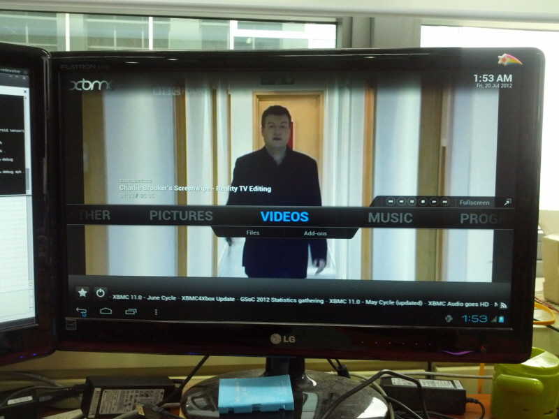
XBMC on the ODROID-X

We had lots of questions on XBMC on ODROID-X from ODROID Forum members. We finally had a chance to test it. 

Realtime streaming channel played well. But mouse click event was ignored by the app:(. So we controlled the UI with a USB keyboard. We will test more contents’ compatibility. 

ODROID-X Pre-Production

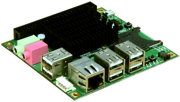
We have started the pre-production this week. Here is the latest picture of ODROID-X.

The background history of adding a heat sink is this. We have performed Full-HD video decoding test only with software. Which was awesome that small embedded quad-core ARM board can decode Full-HD video. But there was a side effect of heat. It is not the normal use environment. But, some heavy users might try. So we have discussed about adding heat sink with ODROID Forum members. They all loved it. So we have decided to add the heat sink without any extra cost.  
It doesn’t affect shipment schedule. Don’t worry. 


Thanks, 

Full-HD Video play with Quad-Core Exynos.

A lot of people inquired about the performance of ARM Cortex A9 1.4Ghz Quad-core.

So we decided to show it with high definition video play ability.
Even the Exynos contains hardwired MPEG4/H.264/WMV decoder inside, we tried pure software driven media decoder.

We’ve tested several different 720p(HD) and 1080p(Ful-HD) video clips with MX player on ODROID-X which has Android 4.0.4.
MX player is one of the best video player in Google Play(Android Market) which is based on the famous FFMPEG media decoder.
They support Multi-core decoding with ARMv7 NEON SIMD feature. It means they utilize the 4 cores in parallel to decode video.

Most of clips could play well with ARMv7 NEON + Multi-core enabled FFMPEG codec library. It is really amazing.
The quad-core can decode Full-HD video even in a small ARM embedded board.
Seek and Sub-title functions are also working well.

Note that most clips contains H.264 video and we could use the hardware accelerated codec too in Android.
But, we performed this test without the hardware accelerator.

Please look into this video.

BTW, we have two issues.
1. Software driven video decoding makes a lot of heat due to heavy computing.
We may need to add a small heatsinks. We will measure the temperature more carefully.

2. 1080p contents in SDHC card doesn’t play well due to limited data transfer rate.
720p contents in SDHC are not a problem.
The eMMC storage has no problem because it is fast enough.

So we need more investigation the HW and SW codecs as well as burden of flash strorage access time.